ยี่ห้อ
 หมวดสินค้า
 ข้อมูล

 (Litech)-120x120.jpg)

 Full-120x120.jpg)
/01 Control Cable/02 With Shield Foil/Multi Cores/Multiconductors Foiled Shielded Single-120x120.jpg)


-120x120.jpg)


-120x120.jpg)
-120x120.jpg)
-120x120.jpg)


-120x120.jpg)
-120x120.jpg)

 ตะกร้าสินค้า
 สินค้าของเรา
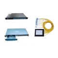
-120x120.jpg "D-Type Indoor Cable (16 ~ 144 cores)")
/03 Ferrule and Fiber Stub/02 Ferrule-120x120.jpg "Ferrule")


/01 NON-INSULATED RING TERMINALS-120x120.jpg "หางปลากลม แบบเปลือย (4.0 - 6.0 sq.mm.) RNBL5-4")


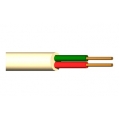
/03 Building Cable/03 Coaxial Cable/04/2-120x120.jpg "JIS Coaxial Cable Video Applications 10C-2V-F")
/01 Control Cable/03 With Shield Foil + Braid/Multipairs Individual Foiled overall Foiled Copper Braided Shielded/IBI12536P-120x120.jpg "สายเคเบิ้ล คอนโทรล มัลติแพร์ แบบมีชิลด์ฟลอยด์แต่ละคู่ ชิลด์ฟลอยด์รวม และ ชิลด์ถักทองแดง 1.25 ตร.มม. (16 AWG) 4 คู่")

x2 to RJ45(F)/Dual Balun Shielded 1.65.6(F)x2 to RJ45(F)-120x120.jpg "Dual Balun Shielded 1.6/5.6(F)*2 to RJ45(F)")
/01 Control Cable/02 With Shield Foil/Multi Pairs/Multipairs Foiled Shielded Single-120x120.jpg "สายมัลติแพร์ แบบมีชิลด์ฟลอยด์ ขนาด 1.25 ตร.มม. (16 AWG) 3 คู่")
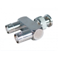
/19 L9 Double Females To Female H Type Adaptor 20mm Center Distance, Discoupled 0dB,5dB,10dB,20dB,25dB/L9 Double Females To Female H Type Adaptor 20mm Center Distance-120x120.jpg "L9 Double Females To Female H Type Adaptor 20mm Center Distance, Discoupled 0dB,5dB,10dB,20dB,25dB")
DIN Female To N Male Adaptor/L29(7;16)DIN Female To N Male Adaptor-120x120.jpg "L29(7/16)DIN Female To N Male Adaptor")


/01 Control Cable/01 Unshield/Multicore Conductor Unshield-120x120.jpg "สายมัลติคอร์ แบบไม่มีชิลด์ ขนาด 0.35 ตร.มม. (22 AWG) 20 คอร์")


/05 Special Cable/04 Multiconductors with Steel Wire Braided Double Sheath/Multiconductors with Steel wire Braided Double sheath 02-120x120.jpg "Multiconductors with Steel Wire Braided Double Sheath 0.50 sq.mm. (20 AWG) 4 Cores")

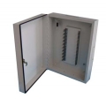
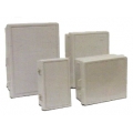
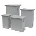
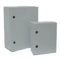
-120x120.jpg "ตู้พักสายโทรศัพท์ ขนาด 30 คู่สาย (พลาสติก)")

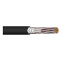
/01 Control Cable/03 With Shield Foil + Braid/Multi Core/Multiconductors Foiled Copper Braided Shielded-120x120.jpg "สายเคเบิ้ล คอนโทรล แบบมีชิลด์ฟลอยด์ และ ชิลด์ถักทองแดง 1.25 ตร.มม. (16 AWG) 30 คอร์")


/01 VINYL-INSULATED RING TERMINALS-120x120.jpg "หางปลากลม แบบหุ้มไวนีล (V-Series) (2.5 - 4.0 sq.mm.) RVS3-5")
/02 Network Cable/03 Computer Cable/03 Multipairs Foiled and Copper braid Shield (CMB)/Multipairs Foiled and Copper braid Shield CMB-120x120.jpg "Multipairs Foiled and Copper Braid Shield (CMB) 22 AWG (7/0.254) 12 Pairs")
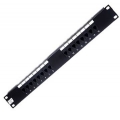
-120x120.jpg "19\" HIGH QUALITY EXPORT RACK 15U (60x60 cm.)")

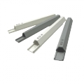
 x สูง(229) x ลึก(75/79) มม.")
 878100")
 x สูง(690) x ลึก(120) มม.")


/01 Control Cable/03 With Shield Foil + Braid/Multi Pairs/Multipairs Foiled Copper Braided Shielded 01-120x120.jpg "สายเคเบิ้ล คอนโทรล มัลติแพร์ แบบมีชิลด์ฟลอยด์ และ ชิลด์ถักทองแดง 0.50 ตร.มม. (20 AWG) 30 คู่")


/22 NON-INSULATED PIN TERMINALS-38x38.jpg)

 ไปรษณีย์ไทย
 สินค้าน่าสนใจ


-38x38.jpg)


-38x38.jpg)
 DBD Registered
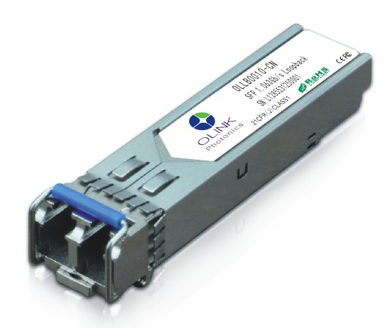
Optical Transceiver SFP 1.063G
 กดเพื่อขยายขนาด |
|
Product Specification Sheet
OLLB0010-CN
1/2/4/8/10G FC and 1G/10G Ethernet Pluggable Transceiver Electrical Loopback Module
PRODUCT FEATURES
Hot pluggable SFP+ footprint
Serial ID
Integrated Module Usage Counter
Bit Rates up to 11.3 Gb/sec
Industrial Temperature Range: -40℃ to +85℃
RoHS Compliant (Lead-Free)
APPLICATIONS
Loopback Testing of 1G/10G Ethernet SFP+ Host Ports.
Loopback Testing of 1/2/4/8/10G FC Host Ports
PRODUCT DESCRIPTIONS
OlinkPhotonics’s Small Form Factor Pluggable (SFP+) OLLB0010-CN Electrical loopback modules provide an effective way of testing the SFP+ ports in the host system by looping back the electrical signal (no optics are included). The units provide basic Serial ID information that attempts to mimic a shortwave GigE /1G/2G FC SFP+ transceiver 4G FC, 8G FC and 10Gb/s Ethernet/FC for manufacturing testing. In addition, the user can query the number of power-up/insertion cycles via the Digital Diagnostics Monitoring Interface in order to ensure optimum module reliability and ascertain device’s useful life.
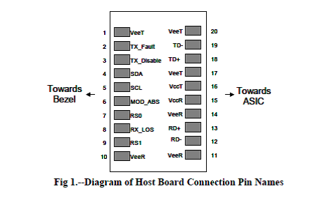
PIN DESCRIPTIONS
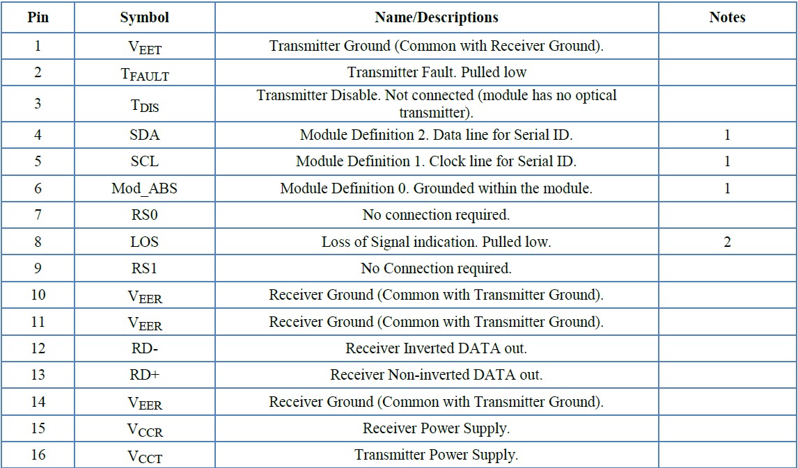
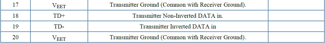
Notes:
1. Should be pulled up with 4.7k – 10kohms on host board to a voltage between 2.0V and 5.5V.
MOD_DEF(0) pulls line low to indicate module is plugged in.
2. LOS is pulled low within the module and therefore will always indicate a received signal.
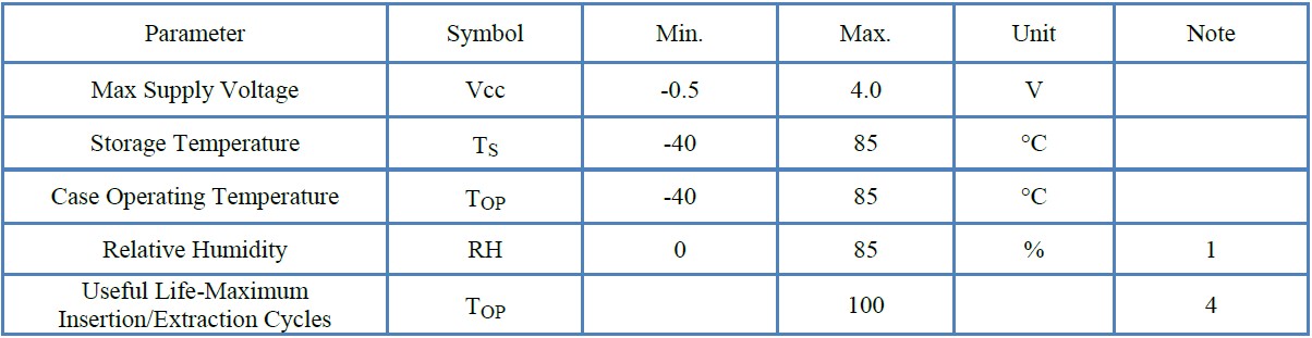
ABSOLUTE MAXIMUM RATINGS
OlinkPhotonics’s SFP+ transceivers have a power supply voltage range of 3.0 V to 3.60V and an
extended operating temperature range from –40°C to 85°C.
ELECTRICAL CHARACTERISTICS (TOP = -40 to 85 ° C, VCC = 3.0 to 3.60 Volts)
Testing Methodology per SFF-8431. Rev 2.2
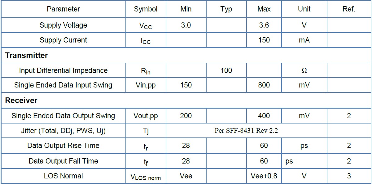
Notes:
1. Non condensing.
2. Into 100 ohms differential termination.
3. LOS is pulled low internally, and will therefore always indicate a received signal.
4. A digital power cycle counter can be found at memory location 254 (MSB)-255(LSB) at device
address A2.
See next section
SERIAL COMMUNICATIONS PROTOCOL
Olink’s SFP+ transceivers support the 2-wire serial communication protocol as defined in the SFF-8472. It is very closely related to the EEPROM defined in the GBIC standard, with the same electrical specifications.
The standard SFP+ serial ID provides access to identification information that describes the transceiver’s capabilities, standard interfaces, manufacturer, and other information.
Additionally, Olink SFP+ transceivers provide a enhanced digital diagnostic monitoring interface, which allows real-time access to device operating parameters such as transceiver temperature, laser bias current, transmitted optical power, received optical power and transceiver supply voltage. It also defines a sophisticated system of alarm and warning flags, which alerts end-users when particular operating parameters are outside of a factory set normal range.
SFF-8472 defines a 256-byte memory map in EEPROM that is accessible over a 2-wire serial interface at the 8 bit address 1010000X (A0h). The digital diagnostic monitoring interface makes use of the 8 bit address 1010001X (A2h), so the originally defined serial ID memory map remains unchanged. The Insertion Cycle Counter is placed in this area, with Byte 120 containing the MSB, Byte 121 the LSB. The interface is identical to, and is thus fully backward compatible with both the GBIC Specification and the SFP Multi Source Agreement. The complete interface is described in Olink Application Note AN-2030: “Digital Diagnostics Monitoring Interface for SFP Optical Transceivers”.
The (OLLB0010-CN) contains additional feature called a power cycle counter. This value is a 2-byte number between 0 and 65535. This counter is located at memory address 254 (MSB) and 255 (LSB) on device address A2. This counter will be automatically incremented every time the transceiver is power cycled. The transceiver can not tell the different between hot swap insertion and system power up. The counter
will maximize at 65535 and will not roll over. The transceiver will not take any action due to the value of this counter. This is only provided as an indicator to the cycle age of the transceiver for the user.
The operating and diagnostics information is monitored and reported by a Digital Diagnostics Transceiver Controller (DDTC) inside the transceiver, which is accessed through a 2-wire serial interface. When the serial protocol is activated, the serial clock signal (SCL, Mod Def 1) is generated by the host. The positive edge clocks data into the SFP transceiver into those segments of the EEPROM that are not write-protected. The negative edge clocks data from the SFP transceiver. The serial data signal (SDA, Mod Def 2) is bi-directional for serial data transfer. The host uses SDA in conjunction with SCL to mark the start and end of serial protocol activation. The memories are organized as a series of 8-bit data words that can be addressed individually or sequentially.
For more information, please see the SFF-8472 documentation.
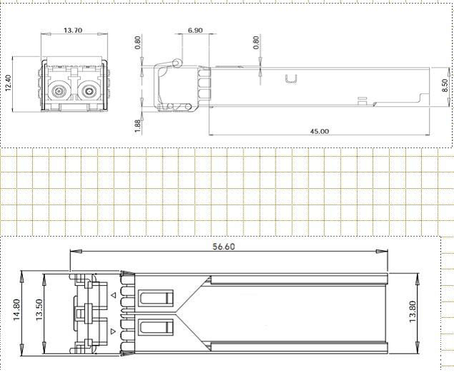
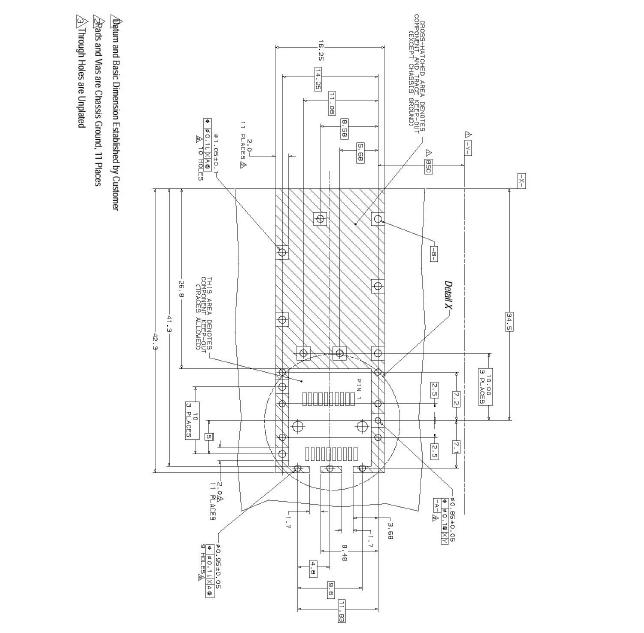
PACKAGE DIMENSIONS
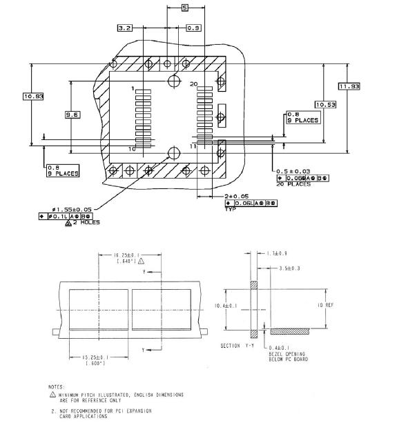
PCB LAYOUT and BEZEL RECOMMENDATIONS
REFERENCE
1. “Specifications for Enhanced 8.5 and 10 Gigabit Small Form Factor Pluggable Module ‘SFP+ ‘”, SFF Document Number SFF-8431, Revision 2.2.
2. “Improved Pluggable Formfactor”, SFF Document Number SFF-8432, Revision 4.2, April 18, 2007.
3. IEEE Std 802.3ae, Clause 52, PMD Type 10GBASE-SR. IEEE Standards Department.
4. “Digital Diagnostics Monitoring Interface for Optical Transceivers”. SFF Document Number SFF-8472, Revision 10.3, December 1, 2007.
5. Directive 2002/95/EC of the European Council Parliament and of the Council, “on the restriction of the use of certain hazardous substances in electrical and electronic equipment”. January 27, 2003.
6. “Application Note AN-2038: Olink Implementation Of RoHS Compliant Transceivers”, Olink Corporation, January 21, 2005.
ความคิดเห็น: คำแนะนำ: HTML จะไม่ถูกแปลง!
ความนิยม: แย่ ดี
ป้อนรหัสในกล่องข้างล่างนี้: